Workdawg
NARWHAL
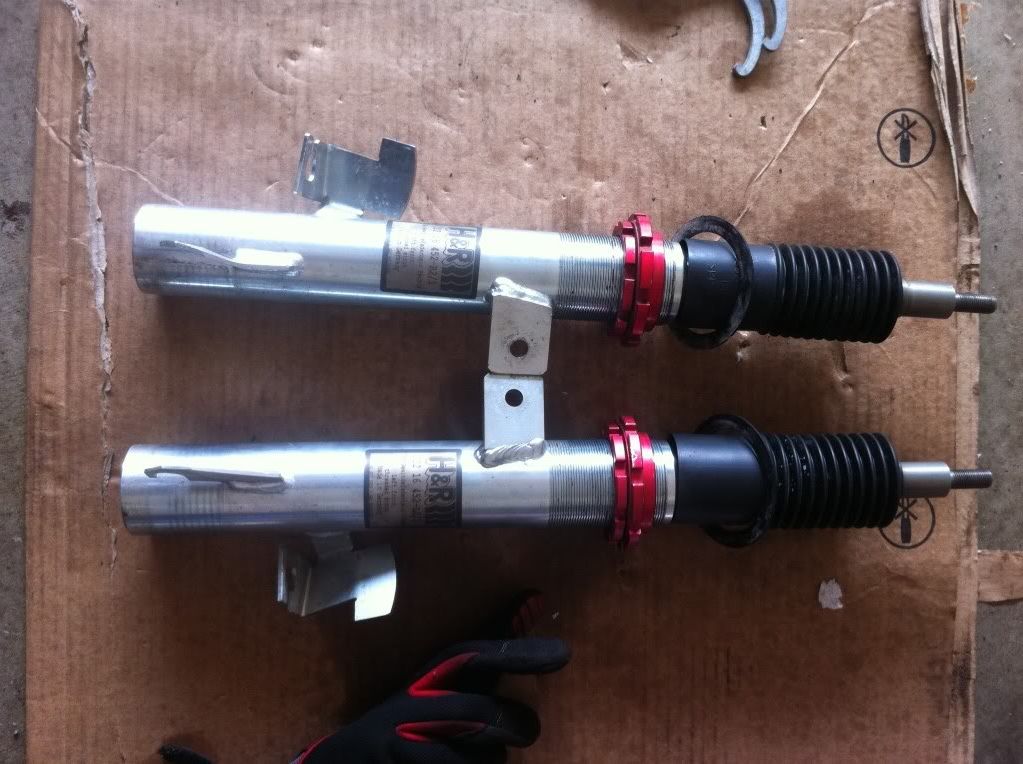
As many of you know, I recently acquired a set of H&R coilovers for my MS3. I decided to tackle the install myself, and after a hiccup the first time around, I finally had some success last night.
Overall it took me about 6 hours. My dad helped me out with the fronts, and I was alone with the rears.
They are height adjustable, and I set them up pretty close to the top both front and back to start out with. To adjust the height in the front, you use the included spanner wrenches to rotate the two red collars away from eachother. Once you have them loosened up, you can adjust the top one to the height you want and then bring the bottom one up to it and tighten them together.
The rears adjust via the included perches. They are threaded and you simply twist the perch up and down on the column. Pretty simple.
The higher up you put the springs, the less of a drop you're going to get.
I have a pic of the fronts, but I forgot to get one of the rears.
I set them both to "5 threads" from the top.
The rears are set probably 2/3 to 3/4 of the way all the way up.
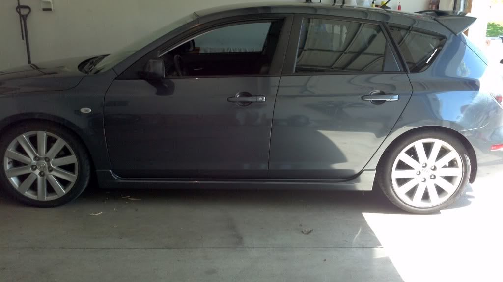
This resulted in about .75" drop front and about .5" drop in the rear after a little bit of driving and about 12 hours to settle. I'll probably adjust it a little bit, but I haven't yet.
Now, on to install info:
1. Tools required
Socket Wrench
Torque Wrench
12mm deep-well socket (rear upper shock mounts)
14mm socket (front upper shock mounts, front endlink bolt, rear endlink to LCA bolt)
17mm socket (front and rear lower shock bolts, rear LCA bolt, rear endlink to rear sway bar bolt)
5mm allen wrench (front endlink bolt, rear swaybar endlink bolts)
6mm allen wrench (front shock hardware)
13mm wrench (rear shock hardware)
14mm wrench (front endlink bolt)
15mm wrench (front shock hardware)
17mm wrench (rear swaybar endlink, if you want to remove the endlink from the swaybar)
Adjustable wrench/vice grips (rear shock hardware)
Flat head screwdriver
Spring compressors
Jack
Jackstands
Big hammer
2x4 around 3' long
Optional:
Breaker Bar (obvious reasons)
PB Blaster (obvious reasons)
Anti-Seize or Some kind of grease (spray down the new shocks to try and prevent them from getting stuck in the steering knuckle in case you need to remove them)
Drill or impact wrench (obvious reasons)
2. The install
It would be wise to start soaking down the required bolts a few days to a week in advance of the install. Since this stuff is all in the wheel wells or under the car, there is potential for a lot of rust in there.
The first step is to get the car up on jackstands. Make sure you've got it completely stable before you get under the car so you don't get yourself hurt.
Remove the wheels and put them out of the way.
2a. Front install
2a1. Removing the stock parts
Once you've got the wheels out of the way, there are 4 things you need to deal with in the front wheel wells before removing the shock.
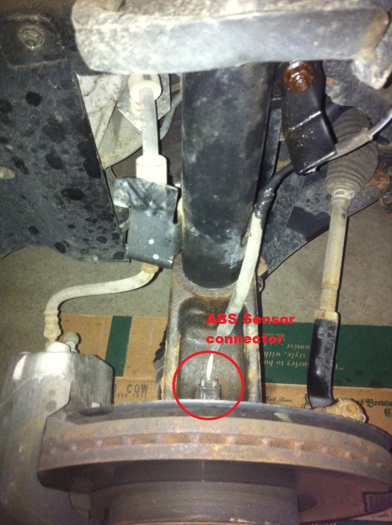
The first is the ABS sensor wire. It's connected to the steering knuckle down in a groove right behind the rotor. There is a clip to depress on the top. Press on the clip and wiggle a little and it should come right out. Hang it up out of the way.
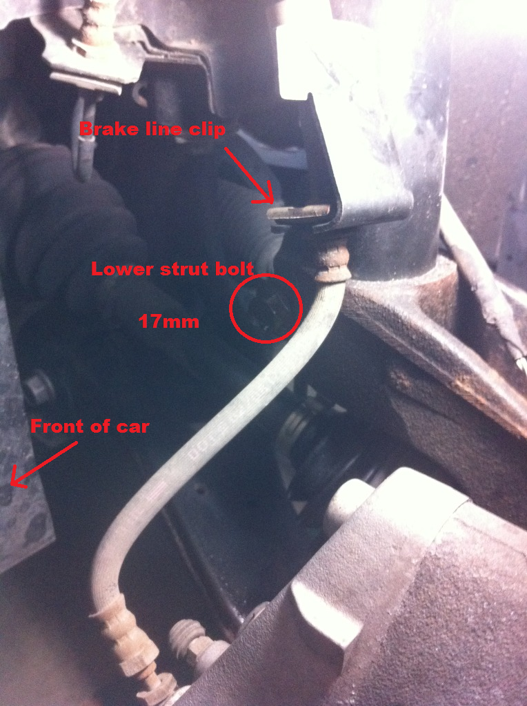
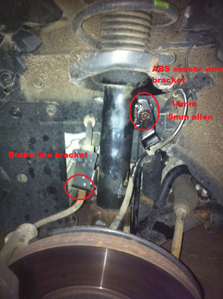
The second thing is the brake line. It's clipped into a bracket on the side of the shock. Since we are removing the shock, obviously you've got to remove the brake line from the stock piece. There is a clip holding the brake line into the bracket. Use a flathead screw driver to pry it out. It might take a bit of prying, but it comes out sideways (towards the front of the car). Once you've got the bracket out, the brake line actually comes out of the bracket through the bottom. Wiggle it around until you get the brake line out of the bracket and set it aside.
The third item is the front sway bar endlink and the bracket that is securing the ABS sensor wire. This is the first bolt you need to deal with. This is a 14mm nut with a hole in the bolt for a 5mm allen wrench. The bolt might be seized up completely if it's too rusty. I recommend taking a breaker bar/socket wrench to it until you get it to spin. You probably won't be able to get this nut off the bolt without the allen wrench though, as it will just spin freely in the endlink. Once you've got it spinning with the socket wrench, switch to the 5mm allen wrench and the 14mm wrench. A ratcheting box wrench is glorious thing to have for this. Once you get the nut off the endlink, take the bracket off the shock, pull the endlink out the back of the shock, and let them hang out of the way. They should rest nicely along the rear of the wheel well.
The fourth item is the bolt that actually holds the shock into the steering knuckle. This bolt is 17mm and it's LONG. Using a ratchet will probably take ya a while, but it'll come out. No real trick to this, just takes a little while.
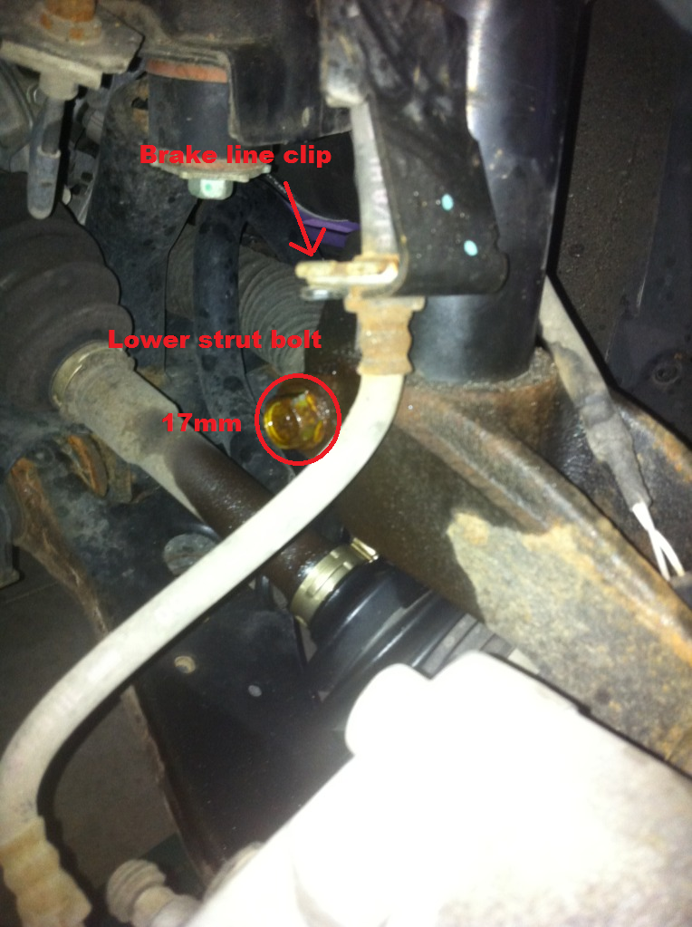
After you have these four items out of the way, now the fun part begins. Separating the shock from the steering knuckle. The stock piece is probably in there REALLY tight. There are a couple ways you can get it out. Some people recommend using the stock scissor jack between the steering knuckle and the shock spring perch to press the two apart. I didn't like doing that as it didn't seem to stay in place very well without putting pressure on the back of the rotor. The shop manual suggested method is to actually beat the steering knuckle with a hammer until the shock gets loosened up enough to get it out. I used a 2x4 and a 2lb hammer (and about 20 mins per side) to accomplish this. The hole the shock goes in in the steering knuckle has a gap in the back. People have suggested that using something to pry it apart a little bit will help the shock come out easier. I tried using the claw side of a hammer a little bit, but went for brute force and it worked eventually.
Once you've got shock loosened up (it should be all but free from the knuckle), go up into the engine bay.
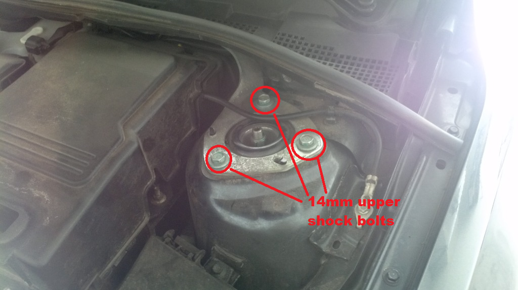
At this point you can take the 3 bolts out of top of the shock tower. They are all 14mm. You don't want to remove the center bolt just yet, that one actually holds the shock together, and we'll get to that later. Once you've got the 3 bolts out of the shock tower, now you need to pull the shock out of the wheel well. Push down on the rotor/knuckle and pull the shock out. It'll probably take some wiggling, but it'll come out.
2a2. Prepare H&R fronts for install
The H&R coilovers use the stock mountings, bearings, and hardware (nuts) for install... so you need to actually disassemble the stock front coilover.
The first step in this process is to use your spring compressors to compress the stock spring so you can disassemble the coilover. The process for this will depend on what type of spring compressors you've got, but it should be pretty straight forward; just make sure you compress them enough that the spring isn't going to go shoot the mount or bearings everywhere when you get the nut off the top.
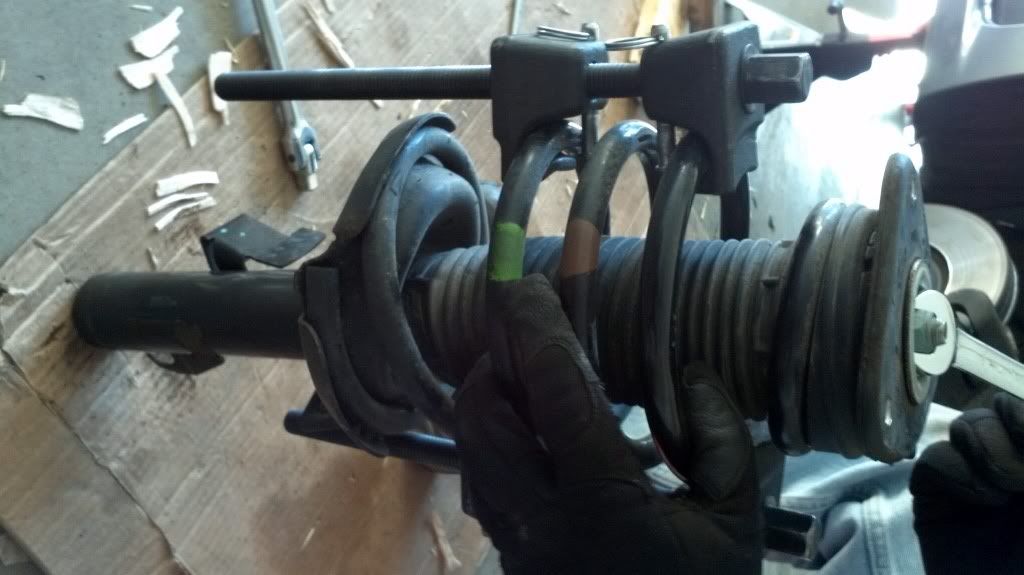
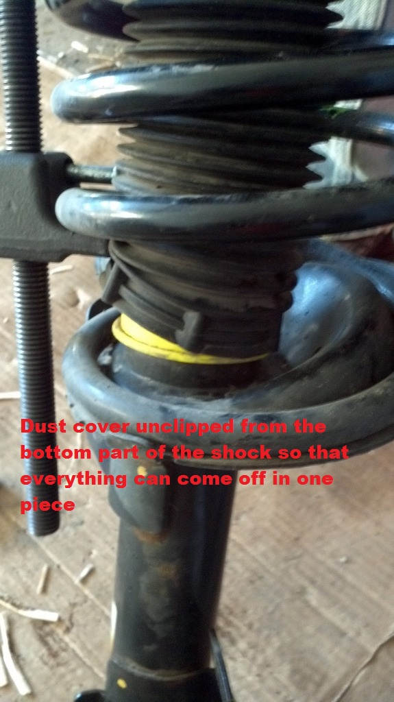
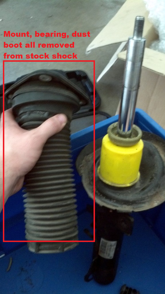
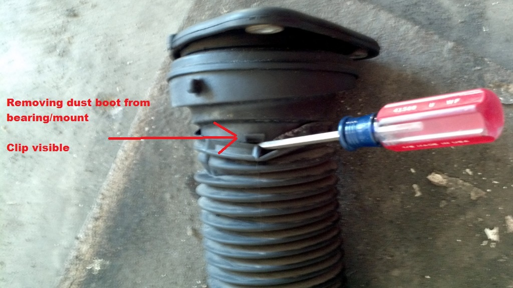
Once you've got the springs compressed, you need to start disassembly. I read many horror stories about bearings shooting all over the place and various things, but I had a pretty easy time with this. My goal was to remove the mount, bearing and dust boot all in one piece. The first thing to do is to get the bottom part of the dust boot off the clips along the bottom of the shock. Use a smallish, flathead screwdriver for this. There are probably about a half dozen little clips that hold the dust boot in place.
Once you've got the boot freed up, remove the center nut from the top of the shock. This nut is a 15mm, and it has a hole in the bolt for 6mm allen wrench. Get those two tools and start removing the nut. Once you've got the nut off the shock, carefully remove the whole top assembly from the shock. Mount, bearing and dust boot. If you can get all these parts off together, you shouldn't have to worry about collecting bearings from all over your garage. Other threads have indicated there are 36 ball bearings in there, just in case you do have issues and need to go hunting.
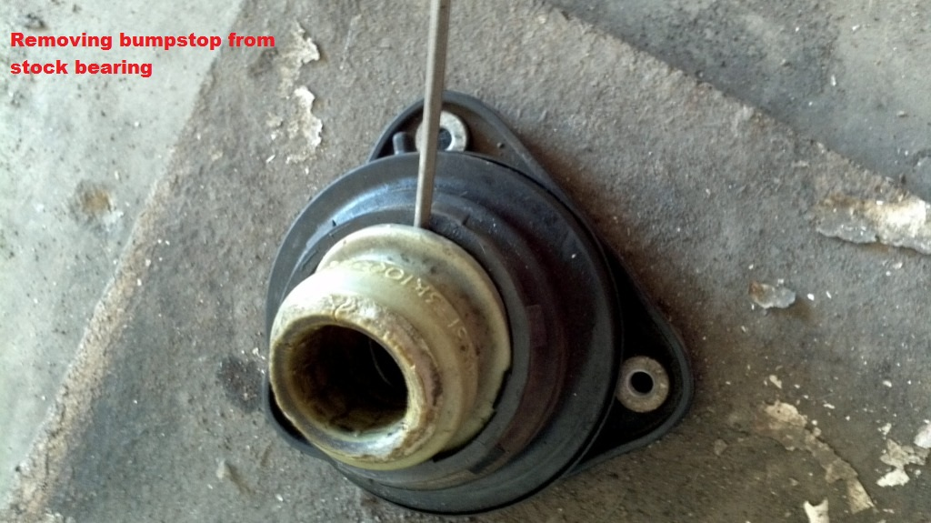
Once you have all that removed, you can take the spring and shock and set them out of the way.Now you need to remove the dust boot and bumpstop from the bearing and mount. (H&R fronts have a built in bumpstop) This is easily accomplished with that same small flathead you just used on the dust boot. Once again, the dust boot has a handful of clips holding it in place along the bearing. Use the screwdriver to pry the boot off the bearing.
After that, you need to pry the bump stop out of the bearing also. Just jam that screwdriver along the edge of the bumpstop and pry it out. My stock bumpstops were actually already broken into two pieces. Once you have the bumpstop out of the bearing, you should be left with the bearing and the mount as one piece, just what you want. Make sure you don't separate the bearing from the mount, as apparently that's bad news.
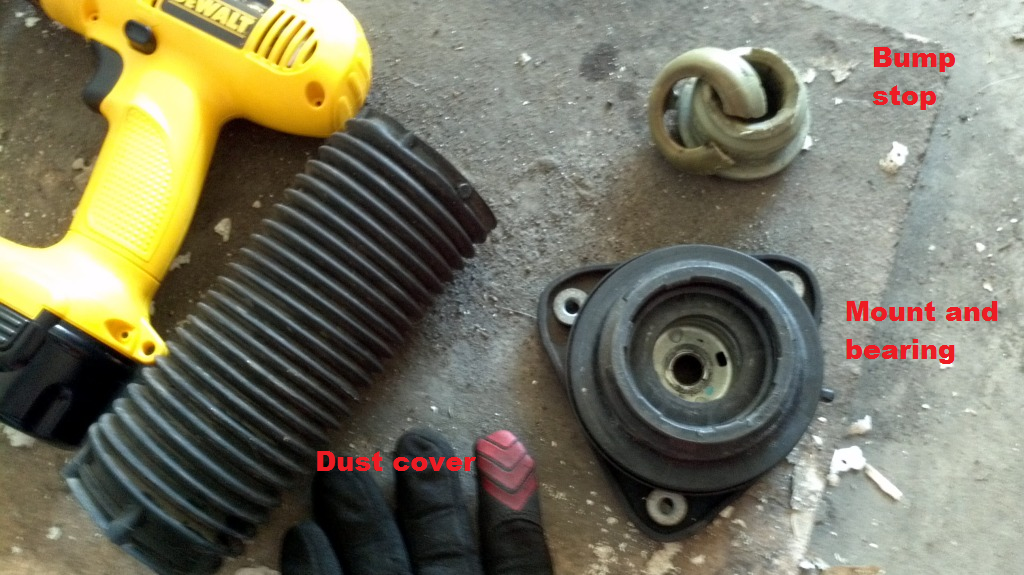
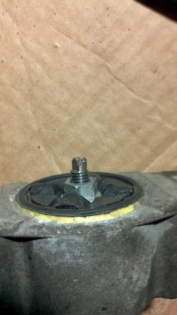
Pic of the dust boot, bump stop, and mount/bearing all separate.
Make sure you have your front H&R shocks set to the height you want and start assembling. The spring goes over the shock, more narrow coil down, so that it rests properly on the red, adjustable collars. Put the mount and bearing on the top of the spring. You also reuse the nut from the stock setup as for this as well. If you are going solo, you probably need to use the spring compressors to compress the spring so you can get the nut on the end of the shock. I had an assistant though, so what we did was a lot quicker. He held the shock upright on the ground while I pressed down on the mount to compress the spring enough to get the nut on. He tightened the nut enough to keep it secure while I held it down. Then we used the 6mm allen wrench and 15mm wrench to tighten it down.
No pics... but it's pretty straight forward.
2a3. Install H&R front coilover
This is essentially the reverse of 2a1, obviously. The first step is to put the new coilover up into the wheel well. The mount has 3 holes for bolts in it in a triangle shape, but it's not an equilateral triangle. Take a note of the way the mount goes up into the tower and line up the holes. Put the bolts in just enough to keep the coilover up into the wheel well but still let the coilover move around. (This is much easier with two people, so one can be underneath in the wheel well to see how to line things up, and another to put the bolts in. You'll need a little bit of play to get the bottom of the shock seated properly in the knuckle. At this point, it's probably a good idea to get the endlink into the bracket on the shock. I forgot to do this the first time, and it was really tough to get it in after the shock was already seated in the knuckle.
Once you've got that taken care of, bring the floor jack over and get it underneath the steering knuckle. Spray the hole in the knuckle where the shock goes, and the shock itself with some grease or anti-seize. Line the shock up with the hole in the knuckle and start jacking up the knuckle slowly. As you jack it up, grab the shock and shake it around to make sure it seats properly. It took me a few tries to get it right, the first time the knuckle kept slanting down and the shock wasn't going in straight. Go slowly and make sure you get them lined up right and jack the knuckle up onto the shock. Keep going until the hole in the bracket on the back of the shock is lined up with the hole in the knuckle.
Once you've got that done, put the bolt back in and tighten it up. 40-54 ft-lbs. Then go back up top into the engine bay and tighten up the 3 bolts into the shock mount. 14-21 ft-lbs. Put the bracket for the ABS wire back onto the endlink bolt and tighten down the nut. 30-40 ft-lbs, though I'm not sure how you measure that accurately since you need to use the 5mm allen wrench and the 14mm open wrench. Get close I guess. Put the brake line into the bracket (bottom up) and secure it with the clip. Lastly, connect the ABS connector back to the steering knuckle. One side done, one to go! (Repeat for the other side in the front)
2b. Rear install
2b1. Removing the stock parts
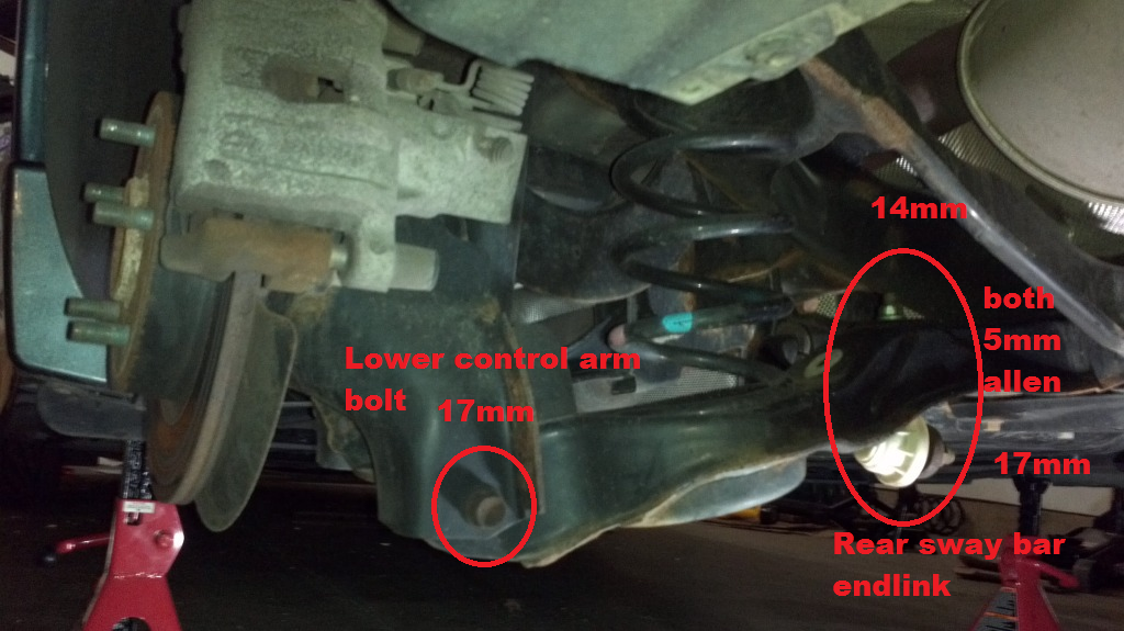
The first step on the rear end is to get the rear sway bar out of the way so you can drop the lower control arms on each side. There are a couple ways to do this. I found it easier to remove the endlinks from the LCA rather than remove the sway bar from the endlinks. Either way you want to do it is fine. Both endlink bolts have a hole in the end for a 5mm allen wrench. The nut on the LCA side is a 14mm nut. The nut on the swaybar side is 17mm. A ratcheting box wrench is also very useful here.
Once you've got the swaybar disconnected from the LCA on both sides, you should be able to rotate it down and towards the front of the car. Just let it hang there.
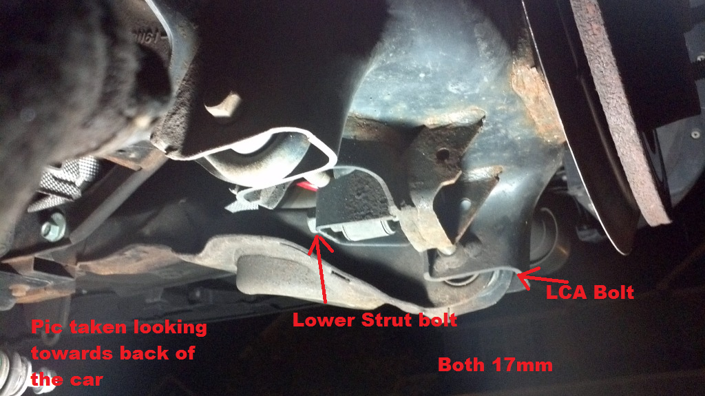
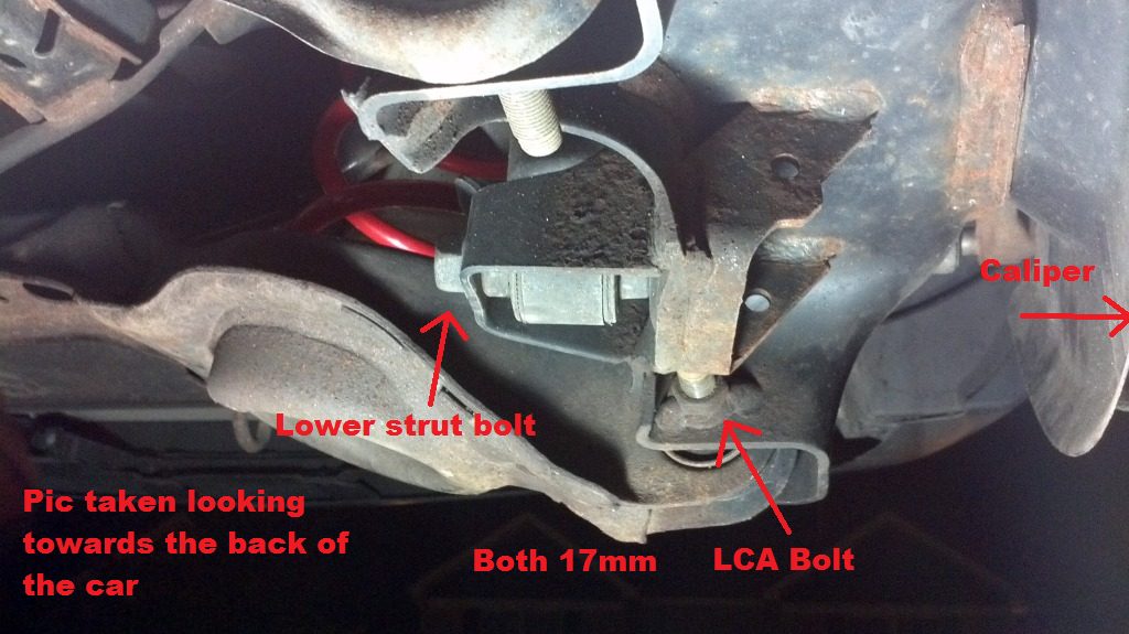
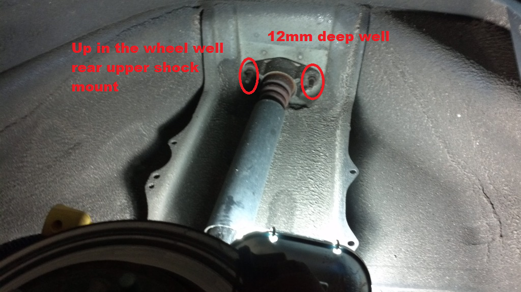
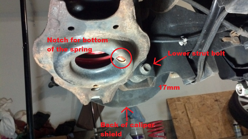
Next, remove the bolt that holds the LCA to the wheel hub (or whatever it's called in the back of the car). It's a 17mm and is another long bolt, but it'll come out eventually. (see the labeled pic above for the location of this bolt) The other walkthrough I read suggested putting your jack underneath the end the LCA and jacking it up a tiny bit just to make sure it doesn't go anywhere when you remove the bolt. You don't want the spring to jump out from between the LCA and the rest of the car. I did this, though when I released the jack the LCA didn't move at all. I had to actually smack it with my fist a couple times to get it to fall down, and even the the spring stayed put. At this point, you should be able to pull the stock spring out. Just set it out of the way. It should have a rubber piece on one end, you shouldn't need that either.
Next up is removing the shock. There's another 17mm bolt underneath the wheel hub (or whatever, again) holding the bottom of the shock. Long bolt #3.
Once it comes out, the shock should be hanging by the two bolts up in the wheel well. So that's the next step. Looking up into the top of the wheel well you'll see two long bolts holding the shock in place. The nuts on these are only 12mm, and because the bolts are so long you need a deep well socket. Remove these two nuts and the shock will be free, almost.
You still have to get it out of the bracket in the wheel hub. I couldn't really figure out an easy way to do this other than to compress the shock by hand until I could get it out of the bracket on the hub and then pulling it out through the bottom. It was rather tough, but not complicated.
2b2. Preparing the H&R rears for install
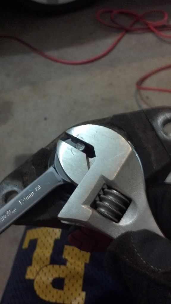
Again, your using the stock mounts and hardware for the H&R bits, so you have to disassemble the stock shock. This was kinda tricky. The nut on the end is 13mm, but unlike the fronts, the rear shocks didn't have an allen wrench hole in them. Instead, the top was flat on two sides. I used a crescent wrench to hold the tip of the shock and a 13mm wrench to turn the nut. The wrench kept slipping, so I ended up actually just holding the nut with the wrench and spinning the crescent wrench instead. Eventually it was loose enough that the nut came off.
In the rear, you want to reuse the dust boot and mount. It's all one piece, so once you get the nut off it's easy sailing. Just put the whole bit over the new H&R shock and tighten down the nut with the same tools. The 13mm wrench and crescent wrench SHOULD work.
I had a little bit of complication on the second side though. I couldn't get the nut onto the shock far enough to grab the tip of the shock with anything. I ended up using my dremel tool and a metal cutting disc to notch the tip of the shock so that I could use a screwdriver to hold the shock while I tighten down the nut with a wrench. It worked great, thankfully.
Anyway, now that you've got the H&R shock assembled with the stock mount and nut, it's time to reinstall.
2b3. Install rear H&R shock and springs
Once again, everything is pretty much backwards from disassembly.
Start out by putting the assembled H&R shock into place the same way you got the stock one out. From underneath. I got the top up into the wheel well and compressed the shock manually until I could get the bottom into the slot in the wheel hub. Then put the two 12mm nuts onto the bolts up in the wheel well to hold the shock up. Tighten them up a little bit, but not all the way just yet.
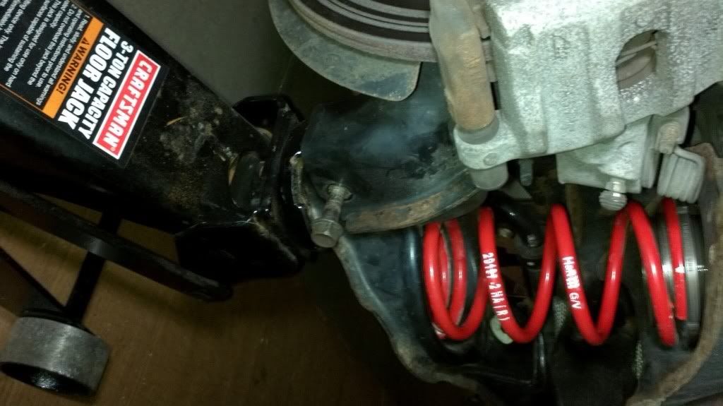
The next step is to put the 17mm bolt back into the bottom of the shock. I used my floorjack to push the shock up high enough to get the bolt in place. Once you've got the bolt in you can move the jack out of the way and tighten the bolt down. 56-74 ft-lbs. Then you can tighten down the 12mm nuts up in the wheel well. 16-21 ft-lbs.
Now that the shock is installed, it's a simple matter of putting the spring in place. I left the stock upper spring perch in place as it seems like the H&R perch matched up nicely with it. The H&R adjustable perch goes up and the other end of the spring just chills out in the LCA.
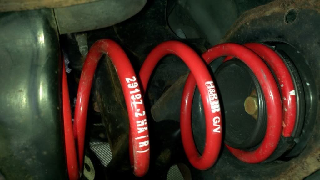
If you look at the bottom of the LCA under the spring, you'll notice that there is a small cutout. Rotate the spring around until the end of the spring seats into the cutout. That should help keep it from moving around.
Now that the spring is in place, you've just got to button everything up. SO CLOSE TO DONE!
Use your jack to lift up the LCA until you get the LCA and wheel hub lined up to replace the 17mm bolt. 56-74 ft-lbs.
Replace the rear sway bar. Put the wheels back on, drop the car, torque the lugnuts and you are done!
Hooray!
3. Final thoughts, tips, etc
The ride is a bit more stiff, but body roll is reduced, it doesn't bounce as much after the bumps. Definitely seems more confident. Overall, I'm quite happy with the ride.
Also, a socket adapter for a drill (or an impact) is a GREAT thing to have. My little 14.4v Dewalt drill was able to make quick work of pretty much all of the bolts after I got them loose, and up until the last few turns to get them torqued down.
6 point sockets instead of 12 point. I was using a 12 point 17mm on the front lower shock bolt with my breaker bar and it was skipping teeth.
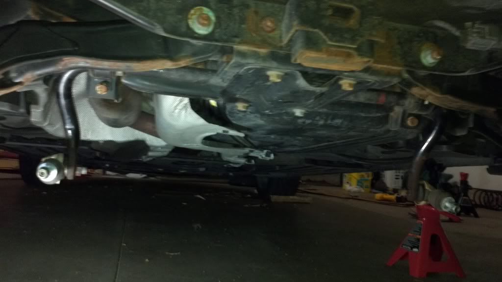
A pic of the car after a few days of driving it:
Overall it took me about 6 hours. My dad helped me out with the fronts, and I was alone with the rears.
They are height adjustable, and I set them up pretty close to the top both front and back to start out with. To adjust the height in the front, you use the included spanner wrenches to rotate the two red collars away from eachother. Once you have them loosened up, you can adjust the top one to the height you want and then bring the bottom one up to it and tighten them together.
The rears adjust via the included perches. They are threaded and you simply twist the perch up and down on the column. Pretty simple.
The higher up you put the springs, the less of a drop you're going to get.
I have a pic of the fronts, but I forgot to get one of the rears.
I set them both to "5 threads" from the top.
The rears are set probably 2/3 to 3/4 of the way all the way up.
This resulted in about .75" drop front and about .5" drop in the rear after a little bit of driving and about 12 hours to settle. I'll probably adjust it a little bit, but I haven't yet.
Now, on to install info:
1. Tools required
Socket Wrench
Torque Wrench
12mm deep-well socket (rear upper shock mounts)
14mm socket (front upper shock mounts, front endlink bolt, rear endlink to LCA bolt)
17mm socket (front and rear lower shock bolts, rear LCA bolt, rear endlink to rear sway bar bolt)
5mm allen wrench (front endlink bolt, rear swaybar endlink bolts)
6mm allen wrench (front shock hardware)
13mm wrench (rear shock hardware)
14mm wrench (front endlink bolt)
15mm wrench (front shock hardware)
17mm wrench (rear swaybar endlink, if you want to remove the endlink from the swaybar)
Adjustable wrench/vice grips (rear shock hardware)
Flat head screwdriver
Spring compressors
Jack
Jackstands
Big hammer
2x4 around 3' long
Optional:
Breaker Bar (obvious reasons)
PB Blaster (obvious reasons)
Anti-Seize or Some kind of grease (spray down the new shocks to try and prevent them from getting stuck in the steering knuckle in case you need to remove them)
Drill or impact wrench (obvious reasons)
2. The install
It would be wise to start soaking down the required bolts a few days to a week in advance of the install. Since this stuff is all in the wheel wells or under the car, there is potential for a lot of rust in there.
The first step is to get the car up on jackstands. Make sure you've got it completely stable before you get under the car so you don't get yourself hurt.
Remove the wheels and put them out of the way.
2a. Front install
2a1. Removing the stock parts
Once you've got the wheels out of the way, there are 4 things you need to deal with in the front wheel wells before removing the shock.
The first is the ABS sensor wire. It's connected to the steering knuckle down in a groove right behind the rotor. There is a clip to depress on the top. Press on the clip and wiggle a little and it should come right out. Hang it up out of the way.
The second thing is the brake line. It's clipped into a bracket on the side of the shock. Since we are removing the shock, obviously you've got to remove the brake line from the stock piece. There is a clip holding the brake line into the bracket. Use a flathead screw driver to pry it out. It might take a bit of prying, but it comes out sideways (towards the front of the car). Once you've got the bracket out, the brake line actually comes out of the bracket through the bottom. Wiggle it around until you get the brake line out of the bracket and set it aside.
The third item is the front sway bar endlink and the bracket that is securing the ABS sensor wire. This is the first bolt you need to deal with. This is a 14mm nut with a hole in the bolt for a 5mm allen wrench. The bolt might be seized up completely if it's too rusty. I recommend taking a breaker bar/socket wrench to it until you get it to spin. You probably won't be able to get this nut off the bolt without the allen wrench though, as it will just spin freely in the endlink. Once you've got it spinning with the socket wrench, switch to the 5mm allen wrench and the 14mm wrench. A ratcheting box wrench is glorious thing to have for this. Once you get the nut off the endlink, take the bracket off the shock, pull the endlink out the back of the shock, and let them hang out of the way. They should rest nicely along the rear of the wheel well.
The fourth item is the bolt that actually holds the shock into the steering knuckle. This bolt is 17mm and it's LONG. Using a ratchet will probably take ya a while, but it'll come out. No real trick to this, just takes a little while.
After you have these four items out of the way, now the fun part begins. Separating the shock from the steering knuckle. The stock piece is probably in there REALLY tight. There are a couple ways you can get it out. Some people recommend using the stock scissor jack between the steering knuckle and the shock spring perch to press the two apart. I didn't like doing that as it didn't seem to stay in place very well without putting pressure on the back of the rotor. The shop manual suggested method is to actually beat the steering knuckle with a hammer until the shock gets loosened up enough to get it out. I used a 2x4 and a 2lb hammer (and about 20 mins per side) to accomplish this. The hole the shock goes in in the steering knuckle has a gap in the back. People have suggested that using something to pry it apart a little bit will help the shock come out easier. I tried using the claw side of a hammer a little bit, but went for brute force and it worked eventually.
Once you've got shock loosened up (it should be all but free from the knuckle), go up into the engine bay.
At this point you can take the 3 bolts out of top of the shock tower. They are all 14mm. You don't want to remove the center bolt just yet, that one actually holds the shock together, and we'll get to that later. Once you've got the 3 bolts out of the shock tower, now you need to pull the shock out of the wheel well. Push down on the rotor/knuckle and pull the shock out. It'll probably take some wiggling, but it'll come out.
2a2. Prepare H&R fronts for install
The H&R coilovers use the stock mountings, bearings, and hardware (nuts) for install... so you need to actually disassemble the stock front coilover.
The first step in this process is to use your spring compressors to compress the stock spring so you can disassemble the coilover. The process for this will depend on what type of spring compressors you've got, but it should be pretty straight forward; just make sure you compress them enough that the spring isn't going to go shoot the mount or bearings everywhere when you get the nut off the top.
Once you've got the springs compressed, you need to start disassembly. I read many horror stories about bearings shooting all over the place and various things, but I had a pretty easy time with this. My goal was to remove the mount, bearing and dust boot all in one piece. The first thing to do is to get the bottom part of the dust boot off the clips along the bottom of the shock. Use a smallish, flathead screwdriver for this. There are probably about a half dozen little clips that hold the dust boot in place.
Once you've got the boot freed up, remove the center nut from the top of the shock. This nut is a 15mm, and it has a hole in the bolt for 6mm allen wrench. Get those two tools and start removing the nut. Once you've got the nut off the shock, carefully remove the whole top assembly from the shock. Mount, bearing and dust boot. If you can get all these parts off together, you shouldn't have to worry about collecting bearings from all over your garage. Other threads have indicated there are 36 ball bearings in there, just in case you do have issues and need to go hunting.
Once you have all that removed, you can take the spring and shock and set them out of the way.Now you need to remove the dust boot and bumpstop from the bearing and mount. (H&R fronts have a built in bumpstop) This is easily accomplished with that same small flathead you just used on the dust boot. Once again, the dust boot has a handful of clips holding it in place along the bearing. Use the screwdriver to pry the boot off the bearing.
After that, you need to pry the bump stop out of the bearing also. Just jam that screwdriver along the edge of the bumpstop and pry it out. My stock bumpstops were actually already broken into two pieces. Once you have the bumpstop out of the bearing, you should be left with the bearing and the mount as one piece, just what you want. Make sure you don't separate the bearing from the mount, as apparently that's bad news.
Pic of the dust boot, bump stop, and mount/bearing all separate.
Make sure you have your front H&R shocks set to the height you want and start assembling. The spring goes over the shock, more narrow coil down, so that it rests properly on the red, adjustable collars. Put the mount and bearing on the top of the spring. You also reuse the nut from the stock setup as for this as well. If you are going solo, you probably need to use the spring compressors to compress the spring so you can get the nut on the end of the shock. I had an assistant though, so what we did was a lot quicker. He held the shock upright on the ground while I pressed down on the mount to compress the spring enough to get the nut on. He tightened the nut enough to keep it secure while I held it down. Then we used the 6mm allen wrench and 15mm wrench to tighten it down.
No pics... but it's pretty straight forward.
2a3. Install H&R front coilover
This is essentially the reverse of 2a1, obviously. The first step is to put the new coilover up into the wheel well. The mount has 3 holes for bolts in it in a triangle shape, but it's not an equilateral triangle. Take a note of the way the mount goes up into the tower and line up the holes. Put the bolts in just enough to keep the coilover up into the wheel well but still let the coilover move around. (This is much easier with two people, so one can be underneath in the wheel well to see how to line things up, and another to put the bolts in. You'll need a little bit of play to get the bottom of the shock seated properly in the knuckle. At this point, it's probably a good idea to get the endlink into the bracket on the shock. I forgot to do this the first time, and it was really tough to get it in after the shock was already seated in the knuckle.
Once you've got that taken care of, bring the floor jack over and get it underneath the steering knuckle. Spray the hole in the knuckle where the shock goes, and the shock itself with some grease or anti-seize. Line the shock up with the hole in the knuckle and start jacking up the knuckle slowly. As you jack it up, grab the shock and shake it around to make sure it seats properly. It took me a few tries to get it right, the first time the knuckle kept slanting down and the shock wasn't going in straight. Go slowly and make sure you get them lined up right and jack the knuckle up onto the shock. Keep going until the hole in the bracket on the back of the shock is lined up with the hole in the knuckle.
Once you've got that done, put the bolt back in and tighten it up. 40-54 ft-lbs. Then go back up top into the engine bay and tighten up the 3 bolts into the shock mount. 14-21 ft-lbs. Put the bracket for the ABS wire back onto the endlink bolt and tighten down the nut. 30-40 ft-lbs, though I'm not sure how you measure that accurately since you need to use the 5mm allen wrench and the 14mm open wrench. Get close I guess. Put the brake line into the bracket (bottom up) and secure it with the clip. Lastly, connect the ABS connector back to the steering knuckle. One side done, one to go! (Repeat for the other side in the front)
2b. Rear install
2b1. Removing the stock parts
The first step on the rear end is to get the rear sway bar out of the way so you can drop the lower control arms on each side. There are a couple ways to do this. I found it easier to remove the endlinks from the LCA rather than remove the sway bar from the endlinks. Either way you want to do it is fine. Both endlink bolts have a hole in the end for a 5mm allen wrench. The nut on the LCA side is a 14mm nut. The nut on the swaybar side is 17mm. A ratcheting box wrench is also very useful here.
Once you've got the swaybar disconnected from the LCA on both sides, you should be able to rotate it down and towards the front of the car. Just let it hang there.
Next, remove the bolt that holds the LCA to the wheel hub (or whatever it's called in the back of the car). It's a 17mm and is another long bolt, but it'll come out eventually. (see the labeled pic above for the location of this bolt) The other walkthrough I read suggested putting your jack underneath the end the LCA and jacking it up a tiny bit just to make sure it doesn't go anywhere when you remove the bolt. You don't want the spring to jump out from between the LCA and the rest of the car. I did this, though when I released the jack the LCA didn't move at all. I had to actually smack it with my fist a couple times to get it to fall down, and even the the spring stayed put. At this point, you should be able to pull the stock spring out. Just set it out of the way. It should have a rubber piece on one end, you shouldn't need that either.
Next up is removing the shock. There's another 17mm bolt underneath the wheel hub (or whatever, again) holding the bottom of the shock. Long bolt #3.
Once it comes out, the shock should be hanging by the two bolts up in the wheel well. So that's the next step. Looking up into the top of the wheel well you'll see two long bolts holding the shock in place. The nuts on these are only 12mm, and because the bolts are so long you need a deep well socket. Remove these two nuts and the shock will be free, almost.
You still have to get it out of the bracket in the wheel hub. I couldn't really figure out an easy way to do this other than to compress the shock by hand until I could get it out of the bracket on the hub and then pulling it out through the bottom. It was rather tough, but not complicated.
2b2. Preparing the H&R rears for install
Again, your using the stock mounts and hardware for the H&R bits, so you have to disassemble the stock shock. This was kinda tricky. The nut on the end is 13mm, but unlike the fronts, the rear shocks didn't have an allen wrench hole in them. Instead, the top was flat on two sides. I used a crescent wrench to hold the tip of the shock and a 13mm wrench to turn the nut. The wrench kept slipping, so I ended up actually just holding the nut with the wrench and spinning the crescent wrench instead. Eventually it was loose enough that the nut came off.
In the rear, you want to reuse the dust boot and mount. It's all one piece, so once you get the nut off it's easy sailing. Just put the whole bit over the new H&R shock and tighten down the nut with the same tools. The 13mm wrench and crescent wrench SHOULD work.
I had a little bit of complication on the second side though. I couldn't get the nut onto the shock far enough to grab the tip of the shock with anything. I ended up using my dremel tool and a metal cutting disc to notch the tip of the shock so that I could use a screwdriver to hold the shock while I tighten down the nut with a wrench. It worked great, thankfully.
Anyway, now that you've got the H&R shock assembled with the stock mount and nut, it's time to reinstall.
2b3. Install rear H&R shock and springs
Once again, everything is pretty much backwards from disassembly.
Start out by putting the assembled H&R shock into place the same way you got the stock one out. From underneath. I got the top up into the wheel well and compressed the shock manually until I could get the bottom into the slot in the wheel hub. Then put the two 12mm nuts onto the bolts up in the wheel well to hold the shock up. Tighten them up a little bit, but not all the way just yet.
The next step is to put the 17mm bolt back into the bottom of the shock. I used my floorjack to push the shock up high enough to get the bolt in place. Once you've got the bolt in you can move the jack out of the way and tighten the bolt down. 56-74 ft-lbs. Then you can tighten down the 12mm nuts up in the wheel well. 16-21 ft-lbs.
Now that the shock is installed, it's a simple matter of putting the spring in place. I left the stock upper spring perch in place as it seems like the H&R perch matched up nicely with it. The H&R adjustable perch goes up and the other end of the spring just chills out in the LCA.
If you look at the bottom of the LCA under the spring, you'll notice that there is a small cutout. Rotate the spring around until the end of the spring seats into the cutout. That should help keep it from moving around.
Now that the spring is in place, you've just got to button everything up. SO CLOSE TO DONE!
Use your jack to lift up the LCA until you get the LCA and wheel hub lined up to replace the 17mm bolt. 56-74 ft-lbs.
Replace the rear sway bar. Put the wheels back on, drop the car, torque the lugnuts and you are done!
Hooray!
3. Final thoughts, tips, etc
The ride is a bit more stiff, but body roll is reduced, it doesn't bounce as much after the bumps. Definitely seems more confident. Overall, I'm quite happy with the ride.
Also, a socket adapter for a drill (or an impact) is a GREAT thing to have. My little 14.4v Dewalt drill was able to make quick work of pretty much all of the bolts after I got them loose, and up until the last few turns to get them torqued down.
6 point sockets instead of 12 point. I was using a 12 point 17mm on the front lower shock bolt with my breaker bar and it was skipping teeth.
A pic of the car after a few days of driving it:
Last edited:

 . This is going to be very helpful when I go to install mine. Incidentally, which repair manual did you get the torque specifications from?